Again, in our example vertically upward reaction force of 60 KN is acting at point C. And the slope of the inclination can be calculated as : Force per unit length x Distance.Ħ. If UDL is acting up to the next point, then there will be a inclined line. If it is point load then vertical line from the end point of the already drawn SFD.

See what kinds of load acting on the next point. In our case the shear force diagram will look like below:ĥ. Unless there is an UDL acting a horizontal line to be drawn till we reach the next point on the beam. as force acting at point A in our case is 20 KN downward, so we have to draw a vertically downward line of 20 unit length ( say 20 mm) at point A. If force acting on the point is downward then the vertical line should go downward or else upward. Draw a vertical line of same length as the value of applied force at the point. Start drawing shear force diagram from any of the extreme ends. So, Rc will be acting upward where as Re will be acting downward in our case.ģ. You will get the vertical reactions in case of our example as: ΣFy – Summation of all the vertical forces ΣFx – Summation of all the horizontal forces Calculate the reaction forces by using the following basic equations: Draw a horizontal line to represent the beam and divide the line by putting points at the following locations:Īnd after that, the above example should look like below:Ģ. Here are simple five steps applicable for drawing almost all types of shear force diagram correctly (Refer the following typical example in connection with the below steps):ġ.
Force diagrams free#
But in order to cross check the output of these packages design engineer should never forget the basics like shear force diagram, bending moment diagram and free body diagram.Ĭorrect shear force diagram (SFD) is very important for designing of machine elements or design of structural members (like truss). She has CAE packages, she has CAD packages, she may have tolerances packages and may be many more. This article will discuss the steps for drawing shear force diagram.Ī design engineer today is much more equipped than she was ever before. You can access the Help page from within the mission by tapping on the Help Me! icon (textbook).Shear force diagram is the most important first step toward design calculations of structural or machine elements.

Force diagrams how to#

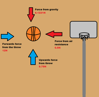
How are the various individual forces best described?.The Physics Classroom, Newton's Laws Unit, Lesson 2, Part c The Physics Classroom, Newton's Laws Unit, Lesson 2, Part b If you are not familiar with this topic, then you should first learn about the topic using our written Tutorial or our Video Tutorial: The student should be able to analyze a physical scenario and determine the relative magnitude of forces acting upon the object in the scenario.You must answer one question from each Question Group to complete the mission. The learning outcomes for this mission are. The mission consists of 39 questions organized into 11 Question Groups. Mission NL5 involves the comparison of the relative magnitude of the individual forces that act upon an object in various physical situations.

Minds On Physics » Newton's Laws » Force Diagrams Mission NL5: Force Diagrams


 0 kommentar(er)
